TM-9-2350-238-20-2 - Page 106 of 495
TM 9-2350-238-20- 2
Section V. WIRING HARNESS AND CABLE REPAI R
2-11. GENERAL.
This section contains instructions on repair of wiring harnesses and cables
(leads). Repair of wiring harnesses and cables consists of replacement of defective connectors ,
shells and terminals or taping cut or worn insulation and exposed wire conductors. Pages 2-6 6
thru 2-72 show exploded views of typical harness and cable connectors used on the vehicle ,
and give procedures for disassembly and assembly of connectors. When soldering is required ,
procedures in TB SIG 222 must be followed .
NOT E
Label cables on multiple receptacles during disassembly to insure proper order
during reassembly .
DISASSEMBL Y
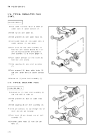
2-12. TYPICAL FEMALE-TYPE PANE L
MOUNTING RECEPTACLE .
1
Drive socket contacts (1) out throug h
rear of insert (2) with pin extractor .
2
Unsolder cable leads from solder well s
on socket contacts (1) .
3
Slide insert out through rear of shel l
assembly (3) .
REASSEMBL
Y
1
2
3
4
Strip cable insulation equal to depth o f
solder wells of socket contacts (1) .
Insert cable leads into solder wells o f
socket contacts (1) and solder .
Push insert (2) into shell assembly (3)
from rear until seated. Groove (4) in in-
sert must be alined with guide in shel l
assembly (3) to ensure proper fit .
Push socket contacts (1) into insert (2 )
from rear until seated .
2-6 6
Back to Top

