TM-9-2350-238-20-2 - Page 153 of 495
TM 9-2350-238-20- 2
9
1 0
1 1
1 2
1 3
1 4
1 5
1 6
1 7
1 8
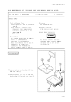
Remove two cotter pins (19), two head -
ed straight pins (20), vertical adjust sea t
guide shoe (21) .
Remove two helical extension spring s
(22) from rigger and gunner seat suppor t
(23) .
Remove two shoulder screws (24) an d
rigger and gunner seat support (23) fro m
cab seat frame (5) .
Remove two cotter pins (25), two head -
ed straight pins (26), and two seat back
rollers (27) .
Remove hexagon plain nut (28) and nee-
dle bearing bolt (29) from cab seat fram e
(5) .
Remove four hexagon capscrews (30) ,
four Iockwashers (31), and two vertica l
adjustment handle connecting links (32) .
Remove two hexagon capscrews (33 )
and two Iockwashers (34), releasing re-
taining strap (35) from cab seat fram e
(5) .
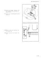
Remove cotter pin (36), flat washer (37) ,
and headed straight pin (38) .
Remove helical spring (39), manual con-
trol lever (40), and headless shoulder pi n
(41) .
Remove knob (42) from manual contro l
lever (40) .
lNSPECTION/REPAI R
1
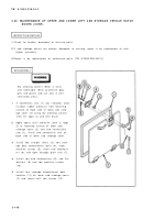
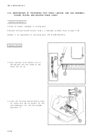
Check for broken, damaged, or missing parts .
2
If cab seat frame is broken, damaged, or missing, repair is by replacement of next higher
assembly .
3
If rigger and gunner seat support is broken, damaged, or missing, repair is by replacemen t
of next higher assembly .
4
Repair is by replacement of authorized parts (TM 9-2350-238-24P-2) which do not meet in -
spection criteria .
2-11 3
Back to Top


