TM-9-2350-238-20-2 - Page 214 of 495
TM 9-2350-238-20- 2
2-55. MAINTENANCE OF BOOM AND WINCH AND MANUAL CONTROL LEVE R
(CONT) .
DISASSEMBLY (CONT )
2
3
4
5
6
7
8
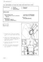
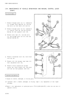
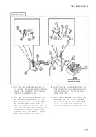
Remove self-locking nut (5) from shifter
fork trigger threaded end rod (6) .
Remove spring pin (7) and winch shif t
control lever trigger (8) from handle (9) .
Remove spring pin (10), shifter fork trig-
ger threaded end rod (6), helical compres-
sion spring (11), and flat washer (12)
from handle (9) .
Remove spring pin (13) from shift contro l
fork (14) and handle (9) .
Remove handle (9) from guide (4) .
Remove shift control fork (14) and tw o
shifter fork thrust washer bearings (15)
from guide (4) .
If necessary, press out two sleeve bear -
ings (16) from guide (4) .
INSPECTION/REPAI R
1
Inspect for broken, damaged, or missin g
parts .
2
If handle is broken, damaged, or missing ,
repair is by replacement of next higher
assembly .
3
If bracket is broken, damaged, or missing ,
repair is by replacement of next higher
assembly .
4
If guide is broken, damaged, or missing ,
repair is by replacement of next higher
assembly .
5
If shift control fork is broken, damaged, o r
missing, repair is by replacement of nex t
higher assembly .
6
If winch control lever winch shift trigger i s
broken, damaged, or missing, repair is by
replacement of next higher assembly .
7
Repair is by replacement of authorize d
parts (TM 9-2350-238-24P-2) which d o
not meet inspection criteria .
2-17 4
Back to Top


