TM-9-2350-256-10 - Page 249 of 796
AN/VIC-3(V) INTERCOMMUNICATION SET OPERATION - Continued
4.
Programming information is transmitted to the radio interfaces and Full Function Crew Stations (FFCS).
5.
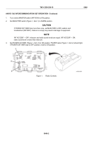
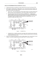
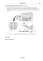
When the Built-In Test (BIT) starts, the display (Figure 4, Item 1) will read "test" as shown in Figure 4. The
BIT, in addition to checking the system configuration for system and Active Noise Reduction (ANR) power,
performs three functions in the following order:
a.
Power-on poll — each crew station FFCS, as well as radios A through F, are polled to determine their
status (connected or disconnected/defective). In other words, the MCS is seeing what's out there.
b.
Electrically Erasable Programmable Read Only Memory (EEPROM) Test — the MCS tests the
read/write capability of its memory by storing and retrieving test data from the EEPROM RAM. If the
MCS cannot store radio access data in its program memory, error messages "err1," "err2," or "err3"
are displayed. These error messages cannot be cleared from the display (Figure 4, Item 1) by
pressing the CHANGE switch (Figure 4, Item 2).
Figure 4.
CD-82/VRC Test.
c.
Configuration Test — the MCS compares the connect status of the crew stations and any radios that
have been programmed into memory via the system configuration procedures with the connect status
as determined by the power-on poll.
6.
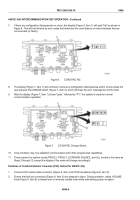
If there are no configuration discrepancies or errors, the display (Figure 5, Item 1) will read "pass" as shown
in Figure 5. This will be immediately followed by the system mode "P1" as shown in Figure 5.
Figure 5.
CD-82/VRC Pass.
TM 9-2350-256-10
0048
0048-5
Back to Top

