TM-9-2350-256-10 - Page 250 of 796
AN/VIC-3(V) INTERCOMMUNICATION SET OPERATION - Continued
7.
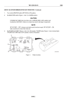
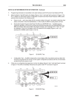
If there are configuration discrepancies or errors, the display (Figure 6, Item 1) will read "fail" as shown in
Figure 6. This will be followed by error codes that determine the crew stations or radio interfaces that are
unconnected (or faulty).
Figure 6.
CD-82/VRC Fail.
8.
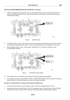
The display (Figure 7, Item 1) will continue to show any configuration discrepancies and/or errors unless the
user presses the CHANGE switch (Figure 7, Item 2), which will clear the error message but not the fault.
9.
After the display (Figure 7, Item 1) shows "pass," followed by "P1," the system is ready for normal
communications operation.
Figure 7.
CD-82/VRC Change Switch.
10.
Crew members may now establish communication within their programmed capabilities.
11.
The procedure for system modes PROG 2, PROG 3, LISTENING SILENCE, and ALL modes is the same as
Steps 2 through 10, except the display of the mode will change accordingly.
Positions of Combat Vehicular Crewman (CVC) Helmet for AN/VIC-3(V)
1.
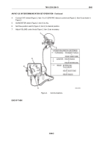
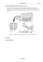
Connect CVC helmet cable connector (Figure 8, Item 4) to FFCS receptacle (Figure 8, Item 5).
2.
Ensure that bail-out connectors (Figure 8, Item 3) are snapped in place. During operation, adjust VOLUME
knob (Figure 8, Item 6) to lowest level to minimize outside noise while maintaining proper reception.
TM 9-2350-256-10
0048
0048-6
Back to Top

