TM-9-2350-256-10 - Page 242 of 796
HYDRAULIC IMPACT WRENCH OPERATION
1.
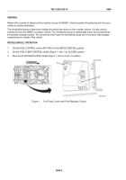
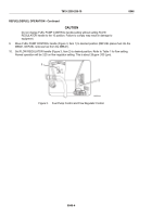
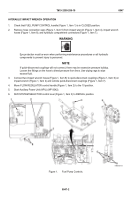
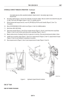
Check that FUEL PUMP CONTROL handle (Figure 1, Item 1) is in CLOSED position.
2.
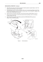
Remove hose connection caps (Figure 1, Item 5) from impact wrench (Figure 1, Item 4), impact wrench
hoses (Figure 1, Item 8), and hydraulic compartment connectors (Figure 1, Item 7).
WARNING
Eye protection must be worn when performing maintenance procedures on all hydraulic
components to prevent injury to personnel.
NOTE
If quick-disconnect couplings will not connect, there may be excessive pressure buildup.
Loosen the fittings on the hose to bleed pressure from lines. Use wiping rags to wipe
excess fluid.
3.
Connect two impact wrench hoses (Figure 1, Item 8) to quick-disconnect couplings (Figure 1, Item 6) on
impact wrench (Figure 1, Item 4) and vehicle quick-disconnect couplings (Figure 1, Item 7).
4.
Move FLOW REGULATOR control handle (Figure 1, Item 2) to the 10 position.
5.
Start Auxiliary Power Unit (APU) (WP 0042).
6.
Shift SYSTEM SELECTOR control lever (Figure 1, Item 3) to REFUEL position.
Figure 1.
Fuel Pump Controls.
TM 9-2350-256-10
0047
0047-2
Back to Top

