TM-9-2350-260-20-1-3 - Page 590 of 783
TM 9-2350-260-20-1-3
BRAKE ADJUSTER ASSEMBLY REPAIR AND REPLACEMENT (Sheet 3 of 6)
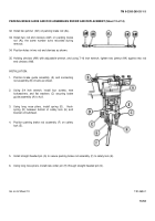
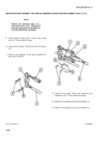
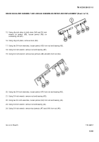
12. Using diagonal cutting piers, remove two cotter pins (S) from lever assembly (R).
Throw cotter pins away.
13. Remove two flat washers (T), pin (U) longer pawl (V), shim (W), and pawl (X) from lever (Y).
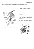
14. Using 9/16 inch wrench, remove screw and
lockwasher (Z).
15. Remove plate (AA).
16. Using hammer and 1/8 inch punch, remove pin (AB).
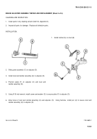
17. Remove guide assembly (AC) and ratchet assembly
(AD) from adjuster assembly (AE).
18. Remove ratchet (A) from stud (AG).
Go on to Sheet 4
TA146350
13-62
Back to Top


