TM-9-2350-260-20-1-3 - Page 601 of 783
TM 9-2350-260-20-1-3
BRAKE EQUALIZER ASSEMBLY AND LINKAGE ASSEMBLIES REPAIR AND REPLACEMENT
(Sheet 8 of 12)
NOTE
Steps 13 through 18 are procedures
for
assembly
of
rod
assembly
identified as rod assembly (T) during
removal.
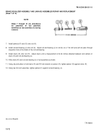
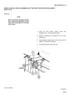
13. Install jamnuts (L) and (M) onto rod (N).
14. Install rod end bearing (P) onto rod (N).
Adjust rod end bearing (P) on rod (N) so a 1/16 inch wire will not pass
through inspection hole in the shank of the rod end bearing.
15. Install clevis (Q) onto rod (N).
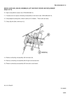
Adjust clevis until a measurement of 15-1/2 inches is obtained between end centers of
clevis (Q) and rod end bearing (P).
16. Aline clevis (Q) and rod end bearing (P) of rod assembly a shown.
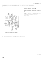
17. Using slip joint pliers to hold clevis (Q) and 3/4 inch wrench on jamnut (M), tighten jamnut (M) against clevis (Q).
18. Using two 3/4 inch wrenches, tighten jamnut (L) against rod end bearing (P).
Go on to Sheet 9
TA146361
13-73
Back to Top

