TM-9-2350-260-20-1-3 - Page 603 of 783
TM 9-2350-260-20-1-3
BRAKE EQUALIZER ASSEMBLY AND LINKAGE ASSEMBLIES REPAIR AND REPLACEMENT
(Sheet 10 of 12)
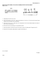
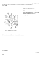
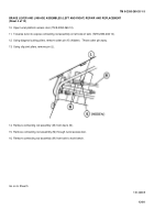
24. Aline hole in link assembly (W) with rod end of 30
inch connecting rod (X).
25. Install screw (Y) and new lockwasher (Z) through
link assembly (W) and connecting rod (X).
26. Aline hole in link assembly (W) rod end of 8-3/4 inch
connecting rod (AA).
27. Install screw (AB) and new lockwasher (AC) through
link assembly (W) and connecting rod (AA).
28. Using 3/4 inch socket, tighten screws (Y) and (AB).
29. Aline holes in plate assembly (AD) with holes in
clevis ends of connecting rods (AA), (AE), (AF).
30. Install three pins (AG).
31. Using long nose pliers, install three new cotter pins
(AH).
32. Return adjuster and all linkage to tank.
33. Install enclosure assembly (page 13-58).
Go on to Sheet 11
TA146363
13-75
Back to Top


