TM-9-2350-261-10 - Page 629 of 761
TM 9-2350-261-10
SERVICE BILGE PUMPS
0086 00
THIS WORK PACKAGE COVERS:
Front Bilge Pump (page 0086 00-1).
Rear Bilge Pump (page 0086 00-3).
Bilge Pumps Operation Check (page 0086 00-5).
INITIAL SETUP:
Maintenance Level
Operator
Tools and Special Tools
C ross Tip Screw driver ( WP 009 4 00, Table
2
, Item 39)
Socket Wrench, 1/2 x 3/4 (WP 0094 00, Table
2
, Item 43)
Socket Wrench Handle, 1/2 inch Drive (WP 0094 00,
Ta ble
2
, I tem 28)
Materials/Parts
Flashlight (WP 0096 00, Item 6)
Personnel Required
Driver
Helper (H)
References
WP 0014 00
WP 0015 00
WP 0047 00
Equipment Condition
Engine stopped (WP 0029 00)
FRONT BILGE PUMP
1.
Lower trim vane (WP 0047 00).
2.
Open power plant access door (WP 0014 00).
3.
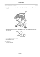
Remove four screws, washers, and front access cover from hull. Use 1/2 inch drive socket wrench handle and 3/4
inch socket.
008600-1
Back to Top


