TM-9-2350-261-20-2 - Page 225 of 1008
REPLACE TACHOMETER CABLE AND ADAPTER — Continued
INSTALLATION
1.
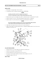
Place adapter (1) on engine adapter, and secure with nut.
2.
Coat flexible drive shaft (2) with grease and install in cable (3) (
WP 0120 00
).
NOTE
Install keyed end of drive shaft (2) in tachometer end of cable (3).
If cable (3) is being replaced, remove all clamps and install them on new cable.
3.
Pull drive shaft (2) part way out of adapter end of cable (3), install slotted washer (4) and flat washer (5) on shaft.
4.
Install new grommet (6) on cable (3). Route cable through power plant and driver’s compartment.
5.
Install new gasket (7) in cable. Install cable on tachometer (8) and right angle drive adapter (1).
NOTE
Place cable at tachometer connection as close to carrier wall as possible to obtain maximum
bend. All other cables and leads should be in front of the tachometer cable.
6.
Align clamp (9) with clamp (10) and secure with screw (11) and new locknut (12).
7.
Align seven cable clamps (13) with power plant and driver’s compartment bulkhead weldnuts. Secure with seven new
lockwashers (14) and screws (15).
FOLLOW-THROUGH STEPS
1.
Install power plant rear access panel (WP 0431 00, WP 0432 00, or WP 0433 00).
2.
Install driver’s power plant access panel (WP 0430 00).
3.
Close power plant front access door and raise trim vane (see your -10).
4.
Start engine to check for proper installation of tachometer cable and adapter (see your -10).
5.
Stop/shutdown engine (see your -10).
END OF TASK
0246 00-3/4 blank
0246 00
TM 9-2350-261-20-2
Back to Top

