TM-9-2350-261-20-2 - Page 487 of 1008
TM 9-2350-261-20-2
REPAIR BATTERY BOX — Continued
0305 00
ASSEMBLY
1.
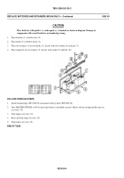
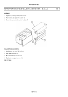
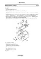
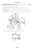
Applyepoxycoatingtobatterybox(1)
.
2.
If removed, install battery box cover rubber bumpers (2) on battery box (1).
3.
Install three grommets (3) on battery box (1). Secure with three screws (4), washers (5), washers (6), and new locknuts
(7).
4.
Install four resilient mounts (8) in frame (9). Place frame in battery box (1) and secure with eight washers (10) and four
screws (11). TIGHTEN SCREWS TO 120–192 LB-IN (14-22 N·M) TORQUE. Use torque wrench and socket.
5.
Place channel divider (12) in battery frame (9). Secure with two washers (13) and screws (14). TIGHTEN SCREWS
TO 84–120 LB-IN (11–14 N·M) TORQUE. Use torque wrench and socket.
6.
Place two latches (15) on side of battery box (1). Secure with four screws (16), washers (17), and new locknuts (18).
FOLLOW-THROUGH STEPS
1.
Install batteries and retainers (WP 0302 00).
2.
Install battery leads and box cover (WP 0295 00).
3.
Start engine (see your -10).
4.
Raise and lock ramp (see your -10).
5.
Stop/shutdown engine (see your -10).
END OF TASK
0305 00-3/4 blank
Back to Top


