TM-9-2350-261-20-2 - Page 528 of 1008
TM 9-2350-261-20-2
REPAIR RECEPTACLE — Continued
0313 00
CLEAN, INSPECT, AND REPAIR
1.
Check wire leads. Look for damaged insulation or broken wires. If wire leads have been taped together, remove tape.
Scrape wire lead covering with your thumbnail to see if covering peels off. Replace bad leads.
2.
Check contact pins, contact sockets, and terminals. Replace burned, bent, or broken parts.
3.
Check shells, sleeves, and nipples. Replace cut, torn, or damaged parts.
ASSEMBLY
NOTE
If replacing lead, cut new wire from bulk supply. Measure original length, gauge, and type
of wire.
1.
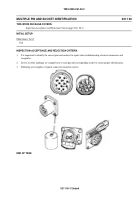
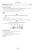
Slide nut (1) over leads (2).
2.
Strip insulation from leads (2) to expose just enough wire to fill holes in contacts (3).
3.
Push leads (2) through grommet (4) and insert in new contacts (3). Solder leads (2) in contacts (3). Use soldering gun.
NOTE
Make sure leads pass through proper lettered holes in grommet.
4.
Align and install grommet (4) in receptacle (5). Secure with nut (1).
FOLLOW-THROUGH STEPS
1.
Use multimeter to perform continuity check before connecting batteries.
2.
Connect battery ground lead (WP 0294 00).
3.
Turn MASTER SWITCH to ON to check for proper receptacle repair.
4.
Turn MASTER SWITCH to OFF (see your -10).
END OF TASK
0313 00-2
Back to Top


