TM-9-2350-261-20-2 - Page 596 of 1008
TM 9-2350-261-20-2
REPLACE COMPARTMENT BLOWER (M577A2 AND M1068 ONLY) — Continued
0335 00
INSPECTION-ACCEPTANCE AND REJECTION CRITERIA
1.
Check adapter (6). Replace cracked adapter.
INSTALLATION
1.
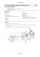
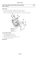
Place adapter (6) on blower (7). Secure with three screws (10) and new locknuts (9).
2.
Place adapter (6), with blower (7) attached, on flapper valve (8). Secure with six screws (5), washers (4), and new
locknuts (3).
3.
Connect circuit 59 lead (2) to blower lead (1).
FOLLOW-THROUGH STEPS
1.
Connect battery ground lead (WP 0294 00).
2.
Turn MASTER SWITCH to ON (see your -10).
3.
Check that blower ope
r
ates properly ( see y our -10).
4.
Turn all switches OFF (see your -10).
5.
Install power plant rear access panel (WP 0433 00).
END OF TASK
0335 00-2
Back to Top


