TM-9-2350-261-20-2 - Page 588 of 1008
TM 9-2350-261-20-2
REPLACE REAR UTILITY OUTLET RECEPTACLES (M577A2 AND
M1068 ONLY) — Continued
0332 00
3.
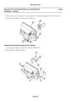
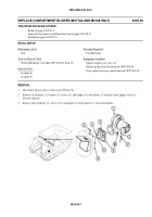
Remove clip (7) and rear main wiring harness (8) from cradle (9).
4.
Remove screw (10), cradle (9), ground lead (11), and lockwasher (12) from hull weldnut. Discard lockwasher.
5.
Remove four screws (13), lockwashers (14), chain (15), receptacle (16), and gasket (17) from rear bulkhead. Discard
gasket and lockwashers.
6.
Remove cap (18) from receptacle (16).
INSPECTION-ACCEPTANCE AND REJECTION CRITERIA
1.
Check leads. Replace frayed, cracked, or broken leads (WP 0312 00).
2.
Check connectors. Replace cracked or broken connectors (WP 0312 00).
INSTALLATION
1.
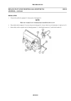
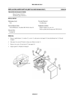
Install cap (1) on receptacle (2).
2.
Place new gasket (3) and receptacle (2) on rear bulkhead. Secure with four new lockwashers (4) and screws (5) with
chain (6) under head of one screw.
3.
Install ground lead (7) and cradle (8) on hull weldnut. Secure with new lockwasher (9) and screw (10).
4.
Place rear main wiring harness (11) in cradle (8). Secure with clip (12).
5.
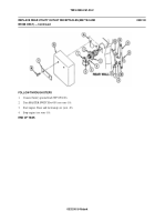
Connect receptacle lead (13) to circuit 37A lead (14) (right receptacle) or circuit 37B lead (14) (left receptacle).
6.
Install rubber shield (15) on hull mount (16). Secure with retainer strip (17) and two screws (18).
0332 00-2
Back to Top


