TM-9-2350-261-20-2 - Page 584 of 1008
TM 9-2350-261-20-2
REPLACE LEAD ASSEMBLY, UTILITY OUTLET (M577A2 AND M1068 ONLY) — Continued
0330 00
INSPECTION-ACCEPTANCE AND REJECTION CRITERIA
1.
Check lead continuity. Use digital multimeter. Replace bad lead.
2.
Check connectors. Replace cracked or broken connectors (WP 0312 00).
INSTALLATION
NOTE
Lead assembly (1) is banded as circuit 37 at master switch panel and circuit 38 at instrument
panel. Make sure it is installed properly.
1.
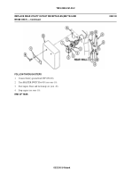
Connect lead assembly (1) to circuit 38 lead (4) at instrument panel (5).
2.
Connect lead assembly (1) to circuit 37 lead (2) at master switch panel (3).
FOLLOW-THROUGH STEPS
1.
Connect battery ground leads (WP 0294 00).
2.
Turn MASTER SWITCH to ON (see your -10).
3.
Turn MASTER SWITCH to OFF (see your -10).
END OF TASK
0330 00-2
Back to Top


