TM-9-2350-261-20-2 - Page 574 of 1008
TM 9-2350-261-20-2
REPLACE BILGE PUMP CIRCUIT BREAKERS — Continued
0327 00
INSTALLATION
1.
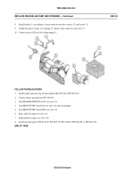
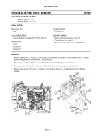
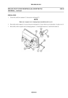
Install two circuit breakers (1) and (2) in distribution box (3). Secure with four screws (4) and new locknuts (5).
2.
Connect circuit 450C lead (6) and circuit 450B lead (7) to top bilge pump circuit breaker (2).
3.
Connect circuit 450A lead (8) and circuit 450 lead (9) to bottom bilge pump circuit breaker (1).
4.
Inspect gasket (10). Replace if damaged.
5.
Place master switch panel (11) on distribution box (3). Secure with eight screws (12), washers (13), and new locknuts
(14).
FOLLOW-THROUGH STEPS
1.
Connect battery ground lead (WP 0294 00).
2.
Turn MASTER SWITCH to ON (see your -10).
3.
Turn on bilge pump switches (see your -10).
4.
Turn all switches OFF (see your -10).
END OF TASK
0327 00-2
Back to Top

