TM-9-2350-261-20-2 - Page 712 of 1008
TM 9-2350-261-20-2
REPLACE T150 TRACK — Continued
0367 00
INSTALLATION
NOTE
A complete track assembly consists of 63 track shoes on the left side and 64 track shoes on the
right side. A flat, level surface about 50 feet (15.24 m) long is needed to assemble track sections.
2.
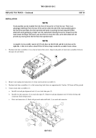
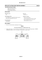
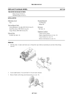
Remove non-mating end connectors (2) from each track shoe assembly (1).
3.
Position track shoe assemblies (1) so that connecting track shoes are approximately 2 inches (50.8 mm) off the ground.
4.
Connect track shoe assemblies (1).
a.
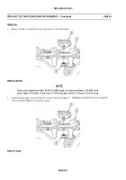
Install two track pin alignment tools (4) over track shoe pins (5).
b.
Install two end connectors (2) on track shoe pins (5). Remove track pin alignment tool (4) before driving end
connectors flush with pin ends.
c.
Drive end connectors (2) flush with pin ends and install bolts (3) on each end connector.
0367 00-2
NOTE
Track assembly can be installed from the front of the carrier or from the rear. There is an
advantage installing it from the rear of the carrier; when the end of the track assembly gets to
the final drive sprockets, the drive sprockets will assist in pushing the track toward the idler
wheel with some guiding by a helper over the road wheels. Moving the carrier forward over the
trackmeansthehelperwillhavetousemoreforce to move the track, as the idler wheel will not
provide any moving force like the final drive sprockets will.
1.
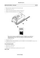
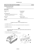
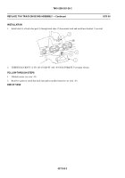
Position track shoe assemblies (1) in a line in back of the carrier. Align track guides of track shoe assemblies between
first pair of road wheels.
Back to Top


