TM-9-2350-261-20-4 - Page 40 of 767
TM 9-2350-261-20-4
REPLACE ELECTRONIC EQUIPMENT HEATER ASSEMBLY AND MOUNTING
BRACKETS (M577A2 ONLY) — Continued
0633 00
INSTALLATION
1.
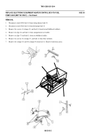
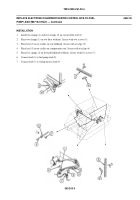
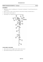
Install elbow (6) on heater (2). Secure with three new lockwashers (22) and screws (21).
2.
Install bracket (12) on radio mount platform. Secure with screw (18), new lockwasher (20), new locknut (19), screw
(1 6), a nd new l ockn ut (1 7).
3.
Install rear support bracket (15) on radio mount platform. Secure with two screws (13) and new locknuts (14).
4.
Install saddle (11) on bracket (12). Secure with two screws (8), three new lockwashers (9), ground lead (5), and two
new locknuts (10).
5.
Install fuel hose and fittings on heater (WP 0626 00).
6.
Install heater (2) in saddle (11) and rear support bracket (15). Secure with two clamps (7).
7.
Install intake and exhaust pipes on heater (WP 0634 00).
8.
Install ground lead (5) on elbow (6). Secure with two new lockwashers (4) and screw (3).
9.
Connect wiring harness (1) to heater (2).
FOLLOW-THROUGH STEPS
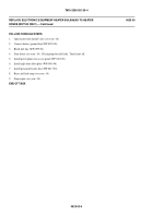
1.
Install heater control box (WP 0630 00).
2.
Connect battery ground lead (WP 0294 00).
3.
Start heater (see your -10). Check that it works properly. Turn heater off.
END OF TASK
0633 00-3/4 blank
Back to Top


