TM-9-2350-261-20-4 - Page 413 of 767
TM 9-2350-261-20-4
REPLACE INVERTER HOUSING A2 TERMINAL BLOCKS TB1 AND
TB2 (M1068 ONLY) — Continued
0728 00
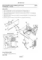
INSTALLATION
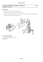
1.
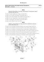
Install terminal block TB2 (7) on cover (4). Secure with four screws (5) and new locknuts (6).
2.
Install terminal block TB1 (3) on cover (4). Secure with two screws (1) and new locknuts (2).
3.
Connect cable W5 leads E1 through E5 (8) and six inverter leads (9) to terminal block TB2 (7). Use wiring diagram.
Secure with ten screws (10).
4.
Insert cable W6 lead E2 (11) and two inverter leads E4 (12) into terminal block TB1 (3). Use wiring diagram. Secure
with two set screws (13).
5.
Install cover (4) on inverter housing (14). Secure with ten screws (15) and new lockwashers (16).
FOLLOW-THROUGH STEPS
1.
Connect battery ground lead (WP 0294 00).
END OF TASK
0728 00-4
Back to Top


