TM-9-2350-261-20-4 - Page 418 of 767
TM 9-2350-261-20-4
R EPAIR POWER CONT ROL EN CLOSU RE FAC EPL AT E AN D
BRACKET (M1068 O NLY)
07 30 00
TH IS WORK PAC KAGE COVER S:
Disassembly (page 0730 00-1).
Assembly (page 0730 00-5).
INITIAL SETUP:
Maintenance Level
Unit
Tools and Special Tools
General Mechanic’s Tool Kit (WP 0780 00, Item 29)
Materials/Parts
Primer (WP 0782 00, Item 54)
Sealing compound (WP 0782 00, Item 67)
Locknut (4)
Locknut (4)
Lockwasher (4)
Lockwasher (6)
Lockwasher (10)
Tie strap (AR)
DISASSEMBLY
1.
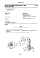
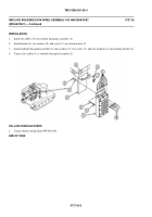
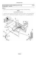
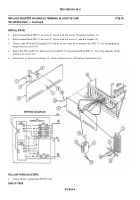
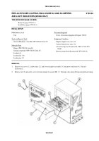
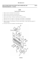
Remove two screws (1), lockwashers (2), and bracket (3) from enclosure (4). Discard lockwashers.
2.
Remove ten screws (5), lockwashers (6), and faceplate assembly (7) from enclosure (4). Lower faceplate (7). Discard
lockwashers.
3.
Remove tie straps (8) from leads as required. Discard tie straps.
4.
Remove four screws (9), locknuts (10), and washers (11) from faceplate hinge (12). Discard locknuts.
073000-1
Engine stopped (see your -10)
Carrier blocked (see your -10)
All external power disconnected
(TM 11-7010-256-12&P)
B attery groun d lead disco nnected (
WP 0294 00)
P
n
e
o
r
i
s
t
o
i
n
d
n
n
e
o
l
C
R
t
e
n
q
e
u
m
i
p
r
i
e
u
d
q
Wiring Diagram (FO-7)
E
s
e
c
n
Power-Generation Equipment Repairer 52D10
R
e
e
r
fe
Back to Top

