TM-9-2350-261-34 - Page 583 of 785
TM 9-2350-261-34
INSTALL COMMANDER’S CUPOLA ARMOR SHIELDS (M113A2, M1059,
AND M1064 ONLY) — Continued
0074 00
INSTALLATION
1.
If four shield mounting holes are already drilled in cupola hatch, remove and discard four 1/2-13 screws and flat washers
from hatch. If mounting holes are NOT drilled, follow Steps 3 - 5.
2.
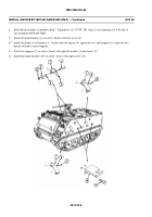
Remove two 5/8-18 screws (1) and washers (2) from outboard support legs of machine gun pintle (3). Discard screws.
Keep flat washers.
3.
Remove machine gun mount and support from cupola. Close cupola (see your -10).
NOTE
All dimensions are in inches with metric equivalents.
4.
Measure and mark four points (A, B, C, and D) on cupola. Measure point positions from four existing screw holes
that secure machine gun support to cupola.
5.
Drill four holes using 27/64 (11 mm) drill. Drill to a maximum depth of 1-1/4 (3 cm). Tap with a 1/2-13 UNC tap to a
minimum depth of 7/8 (22 mm).
0074 00-2
Back to Top


