TM-9-2350-261-34 - Page 585 of 785
TM 9-2350-261-34
INSTALL COMMANDER’S CUPOLA ARMOR SHIELDS (M113A2, M1059,
AND M1064 ONLY) — Continued
0074 00
16. Place front armor shield (1) on a level surface with shield plate supported on two blocks (2) of equal height. Place
blocks about 2 1/2 inches (6 cm) apart with hole in plate centered between blocks. Blocks must support pintle flange of
machine gun mount.
17. Place machine gun mount (3) on shield plate (1). Install machine gun in mount. Center machine gun in shield slot.
18. Place two 1/16 to 1/8 inch (2 to 3 mm) thick spacers (4) between blocks and shield plate so pintle flange is 1/16 to 1/8
inch (2 to 3 mm) below shield plate.
19. Using a level, check to see that pintle flange (3) and shield plate (1) are level. Make sure machine gun is still centered in
slot. Remove machine gun.
20. Use a welding machine and tack weld pintle flange to shield plate (1) in four places. Then weld pintle to upper surface
on plate with not less than 3/16 inch (4 mm) fillet weld all around pintle flange. Weld in accordance with TC 9-237.
21. Raise and lower machine gun mount. Check for interference between ammunition tray and shield plate. Use a hand
grinder and grind off plate, as needed.
22. Touch up any damaged areas with enamel paint. See TM 43-0139.
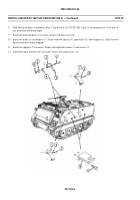
23. Install front shield (1) with machine gun pintle on cupola support. Install travel strap (5) and clamp (6) on right armor
shield (7).
END OF TASK
0074 00-4
Back to Top


