TM-9-2350-261-34 - Page 647 of 785
TM 9-2350-261-34
REPAIR POWER CONTROL ENCLOSURE, REAR PANEL (M1068 ONLY) — Continued
0085 00
3.
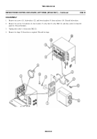
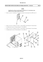
Remove nut (4), lockwasher (5), and leads 31B and 31C (8) from terminal A2 of relay K6 (7).
4.
Remove nut (9), lockwasher (10), and lead 44A (11) from terminal X1 of relay K6 (7).
5.
Remove nut (9), lockwasher (10), and lead 32Q (12) from terminal X2 of relay K6 (7).
6.
Remove two screws (13), locknuts (14), four washers (15), and relay K6 (7) from rear panel (16). Discard locknuts.
7.
Remove tie straps (17) from leads as required. Discard tie straps.
8.
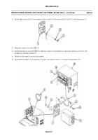
Remove leads 1C and 1D (1) from terminal T1 of contactor relay K1 (2).
9.
Remove leads 2C, 2D, and 2F (3) from terminal T2 of contactor relay K1 (2).
10. Remove leads 8A and 8B (4) from terminalL2ofcontactorrelayK1(2)
.
11. Remove lead 2F (5) from terminal A2 of contactor relay K1 (2).
12. Remove lead 5A (6) from terminal A1 of contactor relay K1 (2).
13. Remove lead 7A (7) from terminal L1 of contactor relay K1 (2).
14. Remove four screws (8), locknuts (9), washers (10), and contactor relay K1 (2) from rear panel (11). Discard locknuts.
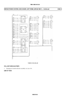
15. Disconnect leads 16A and 16B (12) from terminal A2 of reversing contactor RC1 (13).
16. Disconnect leads 28G and 28D (14) from terminal L2 of reversing contactor RC1 (13).
17. Disconnect lead 28D (14) from terminal A1 of reversing contactor RC1 (13).
18. Disconnect leads 13A and 13D (15) from terminal L1 of reversing contactor RC1 (13).
0085 00-2
Back to Top


