TM-9-2350-277-20-6 - Page 83 of 487
TM 9-2350-277-20-6
REPAIR POWER CONTROL ENCLOSURE FACEPLATE AND BRACKET
(M1068A3 ONLY) — Continued
0828 00
NOTE
All S2 leads are secured with a washer and a screw. The art work shows the installation of
only one washer and one screw.
9.
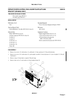
Install toggle switch S2 (39), locking ring (47), lockwasher (48), and nut (49) on faceplate (9).
10. Install circuits 28C and 28F leads (46), lockwasher (41), and screw (42) on terminal 6 of toggle switch S2 (39).
11. Install circuit 29A lead (44), lockwasher (41), and screw (42) on terminal 5 of toggle switch S2 (39).
12. Install circuits 8D and 8F leads (50), lockwasher (41), and screw (42) on terminal 4 of toggle switch S2 (39).
13. Install circuit 13C lead (45), lockwasher (41), and screw (42) on terminal 3 of toggle switch S2 (39).
14. Install circuit 30A lead (43), lockwasher (41), and screw (42) on terminal 2 of toggle switch S2 (39).
15. Install circuit 9E lead (40), lockwasher (41), and screw (42) on terminal 1 of toggle switch S2 (39).
0828 00-8
Change 5
Back to Top


