TM-9-2350-311-20-1 - Page 513 of 1275
TM 9-2350-311-20-1
4-5 POWERPLANT — CONTINUED
f.
Installation — Continued
22
23
24
25
26
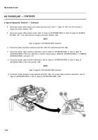
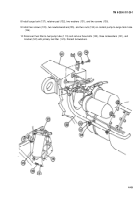
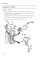
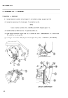
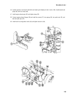
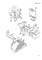
Place shift control in R2 position. Connect shift control rod (103) and install quick-release pin (102).
Move steering wheel to right. Insert steer control rod (100) with boot (101) through bulkhead from engine
compartment and install two quick-release pins (99).
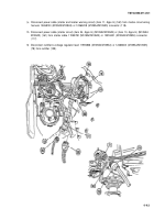
Move throttle control to full open position. Connect throttle valve control rod (98) and tighten nut (97).
Connect tachometer and speedometer flexible drive shafts (94 and 95) and tighten two nuts (96).
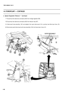
Connect throttle governor control
rod (93) and install quick-release pin (92).
4-52
Back to Top

