TM-9-2350-311-20-1 - Page 511 of 1275
TM 9-2350-311-20-1
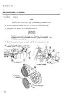
4-5 POWERPLANT — CONTINUED
f. Installation — Continued
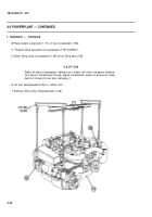
11
12
13
14
15
NOTE
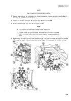
Ensure trunnion cap shims are installed at original location from which they were
removed.
Ensure transmission trunnion caps are installed in proper location as marked on
caps (left front and right front) with mark facing toward front of vehicle.
Primary fuel pump bracket (lifting eye) must be disconnected and removed to
install and properly torque right front trunnion cap screws.
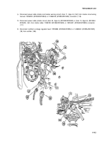
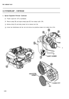
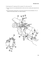
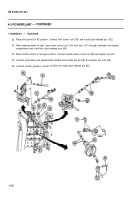
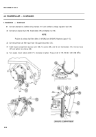
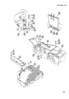
Aline transmission inserts (157) in transmission support assembly (126) and transmission trunnion cap (124).
Install shims (125) if removed, left trunnion cap (124), two flat washers (129), and two bolts(127 and 128). Do
not tighten bolts. Repeat for right support assembly and shim if present.
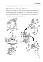
Measure clearance between each trunnion cap (124) and support (126) at forward and rear edges. Clearance
should equal 0.005 to 0.007 in. (0.13 to 0.18 mm).
NOTE
If clearance is less than 0.005 in. (0.13 mm), notify support maintenance. If clearance
is greater than 0.007 in. (0.18 mm), use shims (125) as required to reduce gap.
Torque rear bolt (128) to 85-90 Ib-ft (115-122 N•m).
Torque forward bolt (127) to 85-90 Ib-ft(115-122 NŽm).
4-50
Back to Top

