TM-9-2350-311-20-1 - Page 519 of 1275
TM 9-2350-311-20-1
4-5 POWERPLANT — CONTINUED
f. Installation — Continued
49
50
51
52
53
54
55
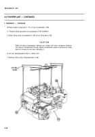
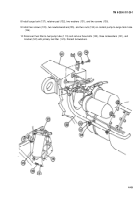
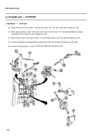
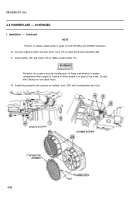
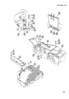
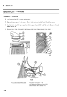
Connect bilge pump hose (39) to connector tube (40). Tighten hose clamp (38).
Install grille support assembly (37), two washers (32), four washers (34), two screws (31 ), two screws (33), two
new Iockwashers (35), and two nuts (36).
WARNIN G
Center front slope plate assembly is heavy. Do not allow center front slope plate to
swing while suspended by hoist and sling. Use caution when working near a sling
under tension to prevent severe injury.
CAUTIO N
Support center front slope plate during installation to prevent equipment damage.
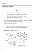
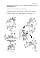
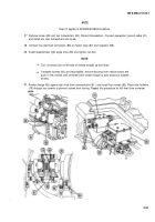
Install center front slope plate assembly (26), seven washers (23), seven screws (22), three washers (25), and
three screws (24).
Install transmission door support (21 ), two screws (20), two washers (1 9), and two nuts (1 8).
Transmission access doors are heavy. If hoisting sling is not available, two personnel
are required to lift and move doors.
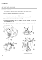
Install right transmission access door (16), two screws (30), two washers (29), and two nuts (28). Repeat
procedure for left transmission access door (17). Close transmission access doors.
Install radiator fan access door (15), six washers (14), and six screws (13).
4-58
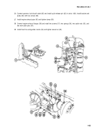
Install engine exhaust grille (12) and 14 screws (11).
Keep clear of equipment when it is being raised or lowered.
To prevent injury, do not
allow grilles or access doors to swing while suspended by lifting device.
WARNING
WARNING
Back to Top

