TM-9-2350-311-20-1 - Page 514 of 1275
TM 9-2350-311-20-1
27
28
29
30
NOTE
Step 27 applies to M109A2/M109A3 Howitzers.
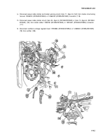
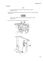
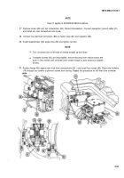
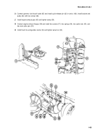
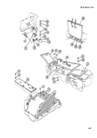
Remove screw (89) and two Iockwashers (90). Discard Iockwashers. Connect powerplant ground cable (91)
and install two new Iockwashers and screw.
Connect four electrical connectors (86) at master relay (87) and regulator (88).
Install speedometer right angle drive (85) and tighten nut (84).
NOTE
Turn universal joint on left side of vehicle straight up and down.
If adapter screws (80) are inaccessible, remove blocking from vehicle tracks and
push or tow vehicle until universal joints rotate enough to gain access to adapter
screws.
Position flange (82) against right final drive universal joint (81 ) and install four screws (80). Place new Iockwire
(79) through four screws to prevent screws from turning. Repeat this procedure for left final drive universal
. .
joint.
.
4-53
Back to Top

