TM-9-2350-311-20-1 - Page 509 of 1275
TM 9-2350-311 -20-1
4-5 POWERPLANT — CONTINUED
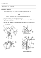
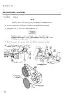
f. Installation — Continued
3
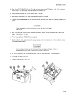
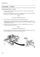
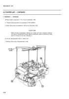
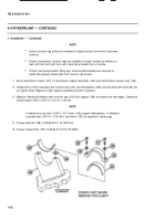
Place coolant surge tank (1 37) on top of
4 “ Position lifting equipment for powerplant
5 Attach lifting sling to powerplant (138) at
powerplant (138).
(138) installation.
four lifting eyes (139).
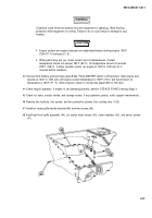
CAUTIO N
Watch all sides of powerplant, making sure it clears hull. Have one person observe
from driver’s compartment through engine compartment access to ensure air intake
duct isn’t forced into fuel tank, damaging it.
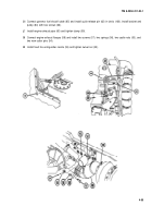
6 Lift and setpowerplant(138) in vehicle hull.
7 Remove lifting sling frompowerplant (138).
4-48
Back to Top

