TM-9-2350-311-20-1 - Page 817 of 1275
8-67 ACCESSORY CONTROL BOX VENTILATOR BLOWER SWITCH LEAD — CONTINUED
a. Removal
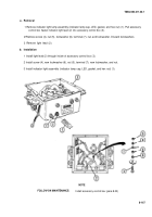
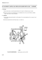
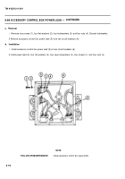
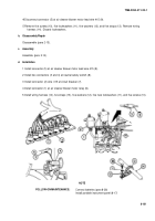
1 Remove three screws (1) and three lead terminals (2) from switch (3). Reinstall screws on switch.
2
Remove four screws (4), four flat washers (5), four Iockwashers (6), and four nuts
(7).
Remove ventilator
blower switch lead (8). Discard Iockwashers.
b. Installation
1 Install ventilator blower switch lead (8), four flat washers (5), four new Iockwashers (6), four screws (4), and
four nuts (7).
2
Install three lead terminals (2) with three screws (1) on switch (3).
NOTE
FOLLOW-ON MAINTENANCE:
Install accessory control box (8-20)
8-172
TM9-2350-311-20-1
Back to Top

