TM-9-2350-311-20-2 - Page 302 of 828
TM 9–2350–311–20–2
5–44
Change 2
5–17 BUFFER ASSEMBLY — CONTINUED
Inspection — Continued
NOTE
Place spacer between shaft collar and recuperator housing.
3
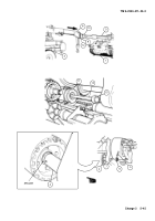
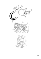
Secure shaft collar (4) with spacer, remove cotter pin (5) and slotted nut (6) from end of recuperator shoul-
dered shaft (7). Discard cotter pin.
4
Position 5-ton wrecker (2) directly in front of howitzer (1). Aline wrecker boom (8) with cannon tube (3).
5
Install fabricated bracket (9) on wrecker boom (8).
6
Extend wrecker boom (8) to muzzle brake (10). Slowly push cannon tube (3) out of battery.
7
Inspect counter recoil buffer (11) for leaks around seals, tube connectors, and buffer piston rod (12). Notify
support maintenance if defects are found.
8
Inspect buffer piston rod (12) for the following:
(a)
Full spring extension (approximately 13 inches (33.02 cm)). Notify support maintenance if spring ex-
tends beyond full extension.
(b)
Paint or foreign matter on buffer piston rod (12) end. Remove all paint and foreign matter found.
(c)
Defective buffer assembly. If buffer piston rod (12) can be pushed in housing easily, then buffer assem-
bly is defective. Notify support maintenance.
9
Inspect buffer piston rod bumper assembly (13) for gouges, mushrooming, and cracks. Notify support main-
tenance if defects are found.
10
Lace cable (14) through muzzle brake (10) and secure to wrecker boom (8).
11
Retract wrecker boom (8) to pull cannon tube (3) back into battery.
12
Secure the shaft collar (4) with spacer, install slotted nut (6) and new cotter pin (5) on recuperator shoul-
dered shaft (7). Remove spacer.
13
Remove cable (14) and fabricated bracket (9) from cannon tube (3) and wrecker boom (8).
Back to Top

