TM-9-2350-311-20-2 - Page 310 of 828
TM 9–2350–311–20–2
5–52
Change 2
5–19 REPLENISHER ACCUMULATOR ASSEMBLY — CONTINUED
c.
Installation — Continued
NOTE
If not precharged before installation proceed with step 8.
8
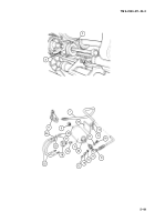
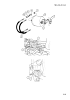
Inject enough hydraulic fluid into replenisher accumulator (23) through check valve (13) to provide fluid
cushion. (Capacity is 2.5 gallons (9.46 l)).
9
Precharge replenisher accumulator (para 19–1).
NOTE
If cap MS20813–1 is present on gas valve, retain for valve cap 9399173.
10
Install valve cap (5).
WARNING
Weight of replenisher accumulator is 65 pounds (30 kg). A second person must support replenisher
accumulator inside cab when installing to prevent injury to personnel.
NOTE
Inside hex nuts and flat washers on U-bolts must not be in contact with cab wall until outside self-
locking nuts have been torqued.
11
Install four inside nuts (26) and four flat washers (25). Tighten four inside nuts.
12
Secure accumulator (23) and two U-bolts (22) to cab wall with four flat washers (21) and four new self-lock-
ing nuts (20) on outside. Torque to 10–15 lb–ft (13–20 N
.
m).
13
Connect hydraulic tube (3) at buffer assembly (4).
14
Close left-hand plug (1) on buffer coupling block (2).
15
Charge replenisher system with hydraulic fluid (TM 9–2350–311–10).
d.
Service
Service replenisher accumulator (23) (para 19–1).
Back to Top


