TM-9-2350-311-20-2 - Page 309 of 828
TM 9–2350–311–20–2
5–51
c.
Installation
1
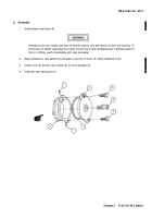
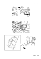
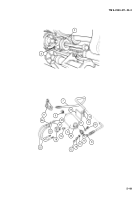
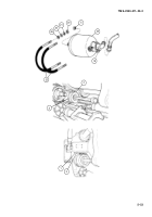
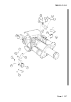
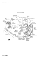
Install coupling (19) and pressure gage (18) on replenisher accumulator (23).
2
Install new preformed packing (14), check valve (13), valve cap (12), and elbow (8) onto adapter (15).
3
Install new preformed packing (17) and plug (16) onto adapter (15).
NOTE
•
Replenisher accumulator assembly can be precharged with dry nitrogen before installation to
cab (para 19–1). Before installing adapter to accumulators, add additional hydraulic fluid to the
shell, approximately 1 gallon (0.836 l).
•
If accumulator replenisher assembly is to be precharged after installation proceed with step 4.
4
Install adapter (15) in housing of replenisher accumulator (23).
5
Attach six clamps (10) to hose assembly (7). Apply sealing compound to shafts of six cap screws (9). Install
six cap screws in six clamps. Torque cap screws to 9 lb-ft (12 N
.
m).
WARNING
Adhesives can burn easily, can give off harmful vapors, and are harmful to skin and clothing. To
avoid injury or death, keep away from open fire and use in well-ventilated area. If adhesive gets on
skin or clothing, wash immediately with soap and water.
6
Apply adhesive to cushioning pad (24) and cab wall. Install cushioning pad on cab wall.
7
Connect hose assembly (7) to manifold (11) and to elbow (8). Tighten swivel fitting.
8
15
12
18
19
13
14
7
16
17
10
9
24
23
11
Back to Top

