TM-9-2350-311-20-2 - Page 305 of 828
TM 9–2350–311–20–2
5–47
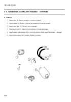
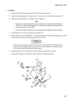
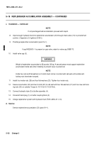
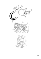
5–19 REPLENISHER ACCUMULATOR ASSEMBLY
This task covers:
a.
Removal
b.
Inspection
c.
Installation
d.
Service
INITIAL SETUP
Tools
Artillery and turret mechanic’s tool kit
(SC 5180–95–CL–A12)
Torque wrench (item 18, Appx H)
Utility pail (item 7, Appx H)
Materials/Parts
Adhesive (item 1, Appx D)
Hydraulic fluid, OHT (item 21, Appx D)
Preformed packings (2) (item 46, Appx G)
Sealing compound, grade C (item 31, Appx D)
Self-locking nuts (4) (item 183, Appx G)
Personnel Required
2
References
TM 9–2350–311–10
a.
Removal
WARNING
•
Wear safety glasses and steel-tipped safety shoes to avoid possible injury while handling equipment.
•
Dry nitrogen tanks are marked with one or two black bands at the top of the tank. Do not use tanks
without black band. In charging replenisher accumulator, use dry nitrogen. Certain other gases will
cause accumulator replenisher to explode, resulting in possible death or serious injury.
NOTE
Replenisher accumulator procedures can be performed while mount and cannon are installed in vehicle.
1
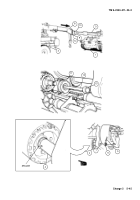
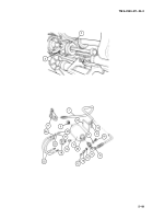
Relieve hydraulic pressure from replenisher accumulator by opening left-hand bleeder plug (1) on buffer coupling
block (2). Catch hydraulic fluid in a utility pail.
2
1
Back to Top

