TM-9-2350-311-20-2 - Page 654 of 828
TM 9–2350–311–20–2
17–16
17–4 NBC CONTROL BOX ASSEMBLY — CONTINUED
d.
Assembly
29
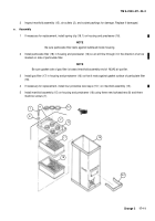
Mount J1 connector (2) and new gasket (40) to bottom of control box (25) using four machine screws (39),
four flat washers (38), four new lockwashers (37), and four hex nuts (36).
30
Mount J2 connector (5) and new gasket (46) to side of control box (25) using four machine screws (45), four
new lockwashers (44), lug terminal (43), four flat washers (42), and four hex nuts (41).
31
Install circuit breaker (30) to inside mounting plate (24) using two machine screws (27), two flat washers
(29), two new lockwashers (28), and two hex nuts (26).
32
Install electromagnetic relay (35) on inside mounting plate (24) using two machine screws (32), two new
lockwashers (34), lug terminal (33) and two hex nuts (31).
33
Reassemble four screws (22), four new lockwashers (23), and mounting plate (24) to control box (25).
34
Install LED (15) and lens (14) in indicator light (13), and mount indicator light on cover (10) using washer
(12) and nut (11).
35
Mount new packing with retainer (21), switchguard (16), and toggle switch (20) to cover (10) by alining lock-
ing tab (19) in hole below switch hole and securing with washer (18) and nut (17).
36
Attach all wires and remove tags. Refer to the following wiring chart for terminal connections. See para 2–16
for soldering instructions when applicable.
37
After installing all wires, secure mounting screws for toggle switch (20), circuit breaker (30), J1 connector (2)
and J2 connector (5) with insulating enamel.
38
Install cover (10) on control box (25) and tighten four captive screws (9).
WIRING CHART
WIRE
FROM
TO
LUG TERMINAL
ITEM
SIZE
SPEC
LENGTH
UNIT
TERM. UNIT
TERM.
MS25036
NO.
AWG
±
0.25
–xxx
REQD
1
6
M81044/9–6–9
5.50
J1
A
CB1
*
–120
1
2
6
M81044/9–6–9
9.50
CB1
*
K1
A2
–120,–119
1 EA
3
16
M81044/9–16–9
6.00
CB1
*
S1
2*
–106,–154
1 EA
4
20
M81044/9–20–9
5.00
DS1
*
K1
X1
–102
1
5
20
M81044/9–20–9
4.50
DS1
*
K1
X2
–102
1
6
16
M81044/9–16–9
5.00
S1
3*
K1
X2
–106
2
7
16
M81044/9–16–9
4.00
K1
X1
K1
GND
–106
1
8
14
M81044/9–14–9
5.00
J2
A
K1
A1
–108
1
9
14
M81044/9–14–9
5.00
J2
B
K1
A1
–112
1
10
14
M81044/9–14–9
5.00
J2
C
K1
A1
–112
1
11
14
M81044/9–14–9
5.00
J2
E
K1
A1
–112
1
12
14
M81044/9–14–9
5.00
J2
F
K1
A1
–112
1
13
16
M81044/9–16–9
3.50
K1
GND
J2
GND
--
--
*Terminals on circuit breaker CB1 and LED DS1 are not designated and, thus, interchangeable. Terminal connections on
switch S1 are also interchangeable.
Back to Top


