TM-9-2350-311-20-2 - Page 727 of 828
TM 9–2350–311–20–2
Change 2
19–19
3
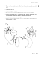
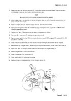
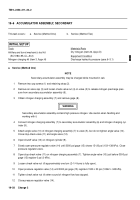
Remove air valve cap (4) from valve body (5). If valve body cannot be reached directly when accumulator
(6) is installed in cab, use accumulator charging extension valve.
NOTE
Be sure ports in bottom cylinder cap are not blocked or plugged.
4
Attach angle valve (7) to valve body (5), but do not tighten. Back out stem (8) of angle valve until stem no
longer contacts valve core (9).
5
Open stop-check valve (10) and close angle valve (11). Open shutoff valve (12).
6
Open pressure regulator valve (13) until 3000 psi gage (14) registers 15 to 20 psi (103 to 138 kPa), then
close pressure regulator valve.
7
Tighten angle valve (7) just before 3000 psi gage (14) registers 0 psi (0 kPa).
8
Turn stem (8) of angle valve (7) clockwise to open valve core (9).
9
Open pressure regulator valve (13) by turning handle clockwise until 3000 psi gage (14) registers 500 to 550
psi (3448 to 3792 kPa).
10
Close pressure regulator valve (13) when sound of nitrogen flowing into accumulator (6) has stopped.
11
Back out stem (8) of angle valve (7) all the way by turning counterclockwise, thereby closing valve core (9).
12
Open angle valve (11) slowly to release pressure in the nitrogen charging assembly (2).
13
Remove angle valve (7) from accumulator (6).
14
Install air valve cap (4) on accumulator (6).
15
Close shutoff valve (12) by turning it clockwise.
16
Remove nitrogen charging assembly (2) from nitrogen cylinder (3).
10
14
13
12
11
2
4
8
9
5
6
7
3
Back to Top

