TM-9-2350-311-20-2 - Page 734 of 828
TM 9–2350–311–20–2
19–26
Change 2
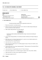
19–5 ACCUMULATOR ASSEMBLY, PRIMARY — CONTINUED
b.
Service (Method Two) — Continued
NOTE
Estimated time required to charge system is 30 minutes or more. System should be charged at am-
bient temperature of weapon.
18
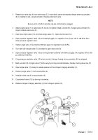
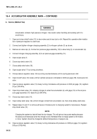
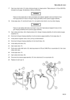
Open angle valve (12) slowly, allowing dry nitrogen to charge system. Raise pressure in 100 psi (690 kPa)
increments until gage (8) on air pressure gage assembly (16) stabilizes at 950 psi (6550 kPa) at 70
°
F
(21
°
C).
WARNING
Failure to close check valve nut on primary accumulator assembly could result in injury to personnel
from high pressure gas.
19
Close check valve nut (4) and shutoff valve (13). Let system remain idle for at least one hour after charging.
WARNING
Failure to open safety-relief valve could result in injury from high pressure trapped in hoses.
20
Open safety-relief valve (17) to bleed pressure from nitrogen charging assembly (7) and air pressure gage
assembly (16).
21
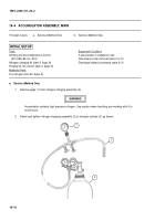
Disconnect nitrogen charging assembly (7) and nitrogen pressure checking device (16) at angle valve (10).
22
Close pressure regulator valve (14) by turning counterclockwise.
23
Disconnect nitrogen charging assembly (7) from shutoff valve (13).
24
Close safety-relief valve (17).
25
Open check valve nut (4).
26
Slowly open safety-relief valve (17), reducing pressure to 900 psi (6206 kPa). Close safety-relief valve.
27
Close check valve nut (4) by turning clockwise.
28
Open safety-relief valve (17).
29
Disconnect air pressure gage assembly (16) from valve (5).
30
Install air valve cap (3) on valve (5).
31
Install two cap screws (1) and retaining strap (2).
Back to Top


