TM-9-2350-311-20-2 - Page 733 of 828
TM 9–2350–311–20–2
19–25
6
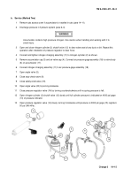
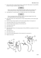
Connect nitrogen charging assembly (7) to air pressure gage assembly (16).
7
Open angle valve (10).
8
Close stop-check valve (11).
9
Close safety-relief valve (17).
10
Open valve (5) on primary accumulator assembly (6) by turning check valve nut (4) counterclockwise.
11
Turn pressure regulator valve (14) counterclockwise until no spring pressure is felt.
12
Open shutoff valve (13) slowly until full cylinder pressure is indicated on 4000 psi gage (18) of pressure
regulator valve (14).
13
Open pressure regulator valve (14) slowly, turning clockwise until pressure on 3000 psi gage (15) reads 50
psi (345 kPa).
14
Open angle valve (12), allowing dry nitrogen to enter primary accumulator assembly (6) until pressure gage
(8) on air pressure gage assembly (16) reads 50 psi (345 kPa). Close angle valve.
15
Open safety-relief valve (17) until all dry nitrogen is bled from primary accumulator assembly (6). Close
safety-relief valve.
16
Repeat steps 13 and 14 to remove all traces of moisture prior to charging system to full pressure with dry
nitrogen.
CAUTION
Charging system too fast will heat dry nitrogen. This will give inaccurate reading because pressure
will decrease when nitrogen cools.
17
Open pressure regulator valve (14) slowly turning clockwise until pressure on 3000 psi gage (15) reads 950
psi (6550 kPa) at 70
°
F (21
°
C).
9
4
5
16
7
6
10
11
12
7
18
13
14
17
8
15
Back to Top

