TM-9-2350-311-20-2 - Page 736 of 828
TM 9–2350–311–20–2
19–28
Change 2
19–6 ACCUMULATOR ASSEMBLY, SECONDARY
This task covers:
a.
Service (Method One)
b.
Service (Method Two)
INITIAL SETUP
Tools
Artillery and turret mechanic’s tool kit
(SC 5180–95–CL–A12)
Nitrogen charging kit (item 3, Appx H)
Materials/Parts
Dry nitrogen (item 22, Appx D)
Equipment Condition
Discharge hydraulic pressure (para 6–3.1)
a.
Service (Method One)
NOTE
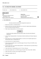
Secondary accumulator assembly may be charged while mounted in cab.
1
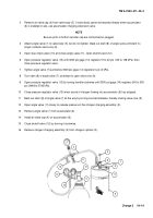
Remove two cap screws (1) and retaining strap (2).
2
Remove air valve cap (3) and loosen check valve nut (4) on valve (5) to release nitrogen precharge pres-
sure from secondary accumulator assembly (6).
3
Obtain nitrogen charging assembly (7) and remove gage (8).
WARNING
Secondary accumulator assembly contains high pressure nitrogen. Use caution when handling and
working with it.
4
Connect nitrogen charging assembly (7) to secondary accumulator assembly (6) and nitrogen charging cyl-
inder (9).
5
Attach angle valve (10) of nitrogen charging assembly (7) to valve (5), but do not tighten angle valve (10).
Close stop-check valve (11) and angle valve (12).
6
Open shutoff valve (13) on nitrogen cylinder (9).
7
Slowly open pressure regulator valve (14) until 3000 psi gage (15) shows 15–20 psi (103–138 kPa). Close
pressure regulator valve.
8
Open stop-check valve (11) on nitrogen charging assembly (7). Tighten angle valve (10) just before 3000 psi
gage (15) register 0 psi (0 kPa).
9
Loosen check valve nut (4) approximately one turn (2–1/4 turns is fully open).
10
Open pressure regulator valve (14) until 3000 psi gage (15) registers 1500
±
50 psi (10342
±
345 kPa).
11
Tighten check valve nut (4) when sound of nitrogen flow has stopped.
12
Close pressure regulator valve (14).
Back to Top

