TM-9-2350-311-34-2 - Page 128 of 552
TM 9-2350-311-34-2
CAB
This task covers:
a. Removal
b. Installation
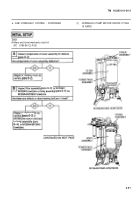
INITIAL SETUP
Tools
Artillery and turret mechanic’s tool kit
(SC 5180-95-CL-A12)
Artillery field maintenance tool kit
(SC 4933-95-CL-A06)
Fabricated cab stand (Figure C-4, Appx C)
Sling, turret lifting (item 21,
Appx F)
Tape (item 35, Appx B)
Materials/Parts
Self-locking bolts (27) (item 90, Appx E)
Self-locking bolts (3) (item 91, Appx E)
Equipment Condition
Park vehicle on level ground
Vehicle MASTER switch to OFF (TM 9-2350-311-10)
CAB POWER switch to OFF (TM 9-2350-311-10)
Disconnect battery ground cable
(TM 9-2350-311-20-1)
Discharge hydraulic pressure (TM 9-2350-311-20-2)
Traversing mechanism cover plate removed
(TM 9-2350-311-20-2)
Turret lock assembly removed (TM 9-2350-311-20-2)
Turret (cab) bearing protective shields removed
(TM 9-2350-311-20-2)
Personnel Required
3
Gunners control bracket removed
(TM 9-2350-311-20-2)
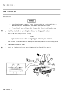
a. Removal
1
Manually elevate cannon assembly (1) to maximum elevation. Remove three self-locking bolts (2) from bot-
tom of trunnion support bracket outside cab. Depress cannon assembly to maximum depression. Discard
self-locking bolts.
2
Drain hydraulic system (TM 9-2350-311-20-2).
3
Remove traversing mechanism (3) (para 9-1).
NOTE
Do not disconnect electrical cables from contact arm assemblies in step 4. Lay contact arm assem-
blies on top of cab electrical contact segment ring. Secure contact arm assemblies with tape.
4
Remove contact arm assemblies (4) (TM 9-2350-311-20-2).
5
Remove 27 self-locking bolts (5) and 27 flat washers (6). Discard self-locking bolts.
Use a lifting device with a capacity of at least 15,000 pounds (6804 kg) to avoid possible injury or
death. A lifting device with insufficient lifting capacity could break due to stress.
Personnel should wear steel-tipped safety shoes and safety glasses to avoid possible injury.
6
Position fabricated cab stand (7) adjacent to cab (8). Position shackles (9) and turret lifting sling (10) behind
cab and fabricated cab stand.
3-2 Change 2
Back to Top


