TM-9-2350-311-34-2 - Page 134 of 552
TM 9-2350-311-34-2
BEARING/RACE RING ASSEMBLY
This task covers:
a. Removal
b. Disassembly
c. Inspection
d. Assembly
e. Installation
INITIAL SETUP
Tools
Artillery and turret mechanic ’s tool kit
(SC 5180-95-CL-A12)
Artillery field maintenance tool kit
(SC 4933-95-CL-A06)
Eye bolts (3) (item 4, Appx F)
Lubrication fittings (3) (item 9, Appx F)
Sling, turret lifting (item 21, Appx F)
Tweezers (item 26, Appx F)
Materials/Parts
Grease (item 21, Appx B)
Lockwire (item 36, Appx E)
Lockwire (item 39, Appx E)
Wooden blocks (3) (item 37, Appx B)
Personnel Required
3
Equipment Condition
Cab removed (Chapter 3)
Contact arm assemblies removed
(TM 9-2350-311-20-2)
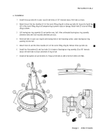
a. Removal
Personnel should wear steel-tipped safety shoes and safety glasses to avoid possible injury.
NOTE
Bearing/race ring assembly components vary between vehicles.
Vehicles with five contact arm assemblies have bearing assemblies with these characteristics:
212 bearing balls are separated by 106 race ring spacers.
Not all vehicles with three contact arm assemblies have same race ring assembly components.
Some vehicles have 212 bearing balls mounted on 106 race ring spacers. Other vehicles have
213 bearing balls mounted on 213 helical compression springs. When maintenance inspec-
tions call for replacement of bearing balls, helical compression springs are replaced by race ring
spacers.
Vehicles having three contact arm assemblies (which have not had helical compression springs
replaced by race ring spacers) have these characteristics:
213 bearing balls are separated by 213 helical compression springs.
4-2 Change 2
Back to Top


