TM-9-2350-311-34-2 - Page 235 of 552
12
13
14
15
16
17
18
19
TM 9-2350-311-34-2
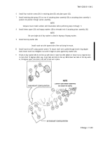
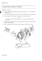
To assemble connecting link (53), connect straight pin (57) to rear universal joint (58). For new parts, drill
straight pin and rear universal joint and install new spring pin (54).
NOTE
Front universal joint and front of straight pin are not drilled for spring pins until spur gears and sector
gears are alined.
Install front universal joint (56) onto straight pin (57) and install straight shaft (55) into front universal joint.
Install connecting link (53) onto bevel gearshaft (79) of actuator assembly (80).
NOTE
l
Install spur gear sector with alinement arrow pointing to front housing assembly.
l
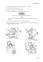
Refer to figure below for alinement of straight shaft.
Coat spur gear sector (6) with grease (item 21.1, or 21.2, Appx B) before installation.
Install ring spacer (48), bearing (47), and spur gear sector (6).
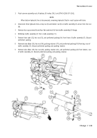
Install shim (46), ring gear retainer (45), and four machine screws (44) in variable recoil housing (17).
Install two sleeve bearings (52) if new parts, Ream to 1.000 ± 0.001-in. (25.4 ± 0.025 mm) ID.
Install two pawls (43), two new flat washers (42), and two machine bolts (41) in variable recoil housing (17).
Torque bolts to 18 lb-ft (24 N•m).
Change 2 5-91
Back to Top


