TM-9-2350-311-34-2 - Page 242 of 552
TM 9-2350-311-34-2
5-13 BUFFER ASSEMBLY
This task covers:
a. Removal
b. Disassembly
c. Inspection
d. Assembly
e. Installation
INITIAL SETUP
Tools
Artillery and turret mechanic ’s tool kit
(SC 5180-95-CL-A12)
Artillery field maintenance tool kit
(SC 4933-95-CL-A06)
Fabricated breech stand (Figure C-3, Appx C)
Materials/Parts
Cotter pin (item 48, Appx E)
Key washers (2) (item 121, Appx E)
Packing retainers (2) (item 61, Appx E)
Preformed packing (item 65, Appx E)
Preformed packing (item 99, Appx E)
Retaining ring (item 16, Appx E)
Retaining ring (item 17, Appx E)
Seal replacement parts kit (item 140, Appx E)
Seals (2) (item 162, Appx E)
Spring pins (2) (item 25, Appx E)
Personnel Required
2
Equipment Condition
Drain replenisher hydraulic system (para 5-12)
Turret lock in locked position (TM 9-2350-311-10)
a. Removal
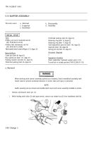
When working with cannon assembly pushed out of battery, block breechblock assembly with
breech stand to prevent accidental elevation of cannon tube and injury to personnel.
NOTE
Buffer assembly can be removed and installed with mount and cannon assembly installed in vehicle.
1
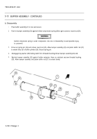
Remove and discard cotter pin (1).
2
While holding shaft collar (2) with pipe wrench, remove rear slotted nut (3) from shouldered shaft (4).
5-98 Change 2
Back to Top

