TM-9-2350-311-34-2 - Page 238 of 552
TM 9-2350-311-34-2
5-12 VARIABLE RECOIL ASSEMBLY - CONTINUED
e. Installation - Continued
Use gloves or rags to grip inner orifice. Edge of inner orifice is extremely sharp and could cause
injury.
12
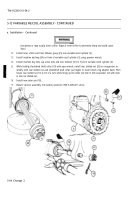
Install inner orifice and front follower group (25) into variable recoil cylinder (3).
13
Install machine bushing (24) on front of variable recoil cylinder (3) using spanner wrench.
14
Install machine key (23), cap screw (22), and new lockwire (21) in front of variable recoil cylinder (3).
15
While holding shouldered shaft collar (19) with pipe wrench, install rear slotted nut (20) on recuperator as-
sembly until rear slotted nut and shouldered shaft collar just begins to touch breech ring adapter band. Then
loosen rear slotted nut 1/6 to 2/3 of a turn while lining up the cotter pin hole in the recuperator rod with slots
in the rear slotted nut.
16
Install new cotter pin (18).
17
Return cannon assembly into battery position (TM 9-2350-311-20-2).
5-94 Change 2
Back to Top

