TM-9-2350-311-34-2 - Page 304 of 552
TM 9-2350-311-34-2
6-10 EQUILIBRATION MANIFOLD ASSEMBLY - CONTINUED
a. Disassembly - Continued
4
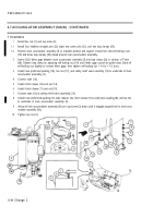
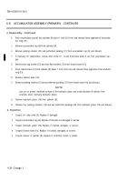
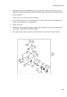
Remove preformed packing (5), packing retainer (6), and preformed packing (7) from valve (3) and discard.
5
Remove two spring pins (8), drain valve knob (9), and equilibrator valve knob (10) from manifold (4). Discard
spring pins.
b. Inspection
1
Inspect manifold (4). Replace equilibration manifold assembly (11) if manifold is cracked or damaged.
2
Inspect valve (3). Replace if distorted, cracked, or threads damaged.
c. Assembly
1
2
3
4
5
6
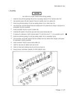
Install new preformed packing (7), new packing retainer (6), and new preformed packing (5) on valve (3).
Coat valve (3) with hydraulic fluid and carefully install in manifold (4).
Install outer nut (2) on valve (3).
Install drain valve knob (9), equilibrator valve knob (10), and two new spring pins (8) on manifold (4).
Install lew lockwire (1) to secure outer nut (2) to valve (3).
Adjust equilibration manifold assembly (11) (para 6-10d.).
d. Adjustment
NOTE
Be careful not to get dirt or other foreign material into valve ports.
1
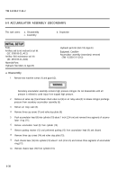
Turn drain valve knob (9) clockwise to close drain port (12).
2
Turn equilibrator valve knob (10) to open valve.
3
Plug ACC port (13) and MANPUMP port (14).
Hydraulic fluid flow from RET port will be under high pressure. Use caution to prevent serious injury.
4
Connect hose to RET port (15) and direct flow into a utility pail.
NOTE
If opening pressure of valve is not obtained in step 5, perform steps 6 through 10 to adjust opening
pressure.
6-42
Back to Top


