TM-9-2350-311-34-2 - Page 296 of 552
TM 9-2350-311-34-2
6-7 ACCUMULATOR ASSEMBLY (MAIN) - CONTINUED
f. Installation
1
1.1
1.2
2
3
4
5
6
7
8
9
10
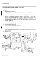
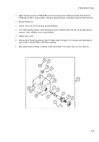
Install hex nut (1) and cap screw (2).
Install four headless straight pins (22) eight new cotter pins (21), and two loop clamps (20).
Position main accumulator assembly (3) in installed position and support. Install two new self-locking nuts
(19) and draw loop clamps (20) closed around main accumulator assembly.
Insert 0.002 feeler gage between main accumulator assembly (3) and loop clamp (20) in vicinity of T-bolt
(38). Tighten loop clamp by adjusting self-locking nut (19) until feeler gage cannot be pulled loose. Back off
self-locking nut slightly to remove feeler gage, then tighten self-locking nut 1-1/4 to 1-1/2 turns.
Install new preformed packing (18), hex nut (17), and safety relief valve assembly (13) to underside of main
accumulator assembly (3).
Connect tube (16).
Install clinch sleeve (15) and nut (14).
Install clinch sleeve (11) and nut (10).
Connect tube (12) at safety relief valve assembly (13).
Install new preformed packing (7), tube reducer (6), clinch sleeve (5) nut (4) tube coupling (8), and tee (9)
to underside of main accumulator assembly (3).
At top of main accumulator assembly (3) turn cap screw (2) down until it engages tapped hole in main accu-
mulator assembly fully.
Tighten hex nut (1).
6-34 Change 2
Back to Top

