TM-9-2350-311-34-2 - Page 290 of 552
TM 9-2350-311-34-2
6-6
ACCUMULATOR ASSEMBLY (MANUAL PUMP) - CONTINUED
c. Assembly
1
2
3
4
5
6
7
8
9
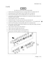
Do not distort preformed packings when installing. Be careful not to damage machined surfaces of
hydraulic piston, inside surface of cylinder, or threads at each end of cylinder. Avoid damage when
inserting hydraulic piston into cylinder.
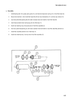
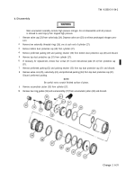
Coat four new preformed packings (13) with hydraulic fluid. Install four preformed packings and six new
packing retainers (12) on hydraulic piston (11).
Install hydraulic piston (11), cylinder tube nipple (10), and linear cap (9) in cylinder (8).
Ensure grooves in hydraulic piston (11) aline with holes in cylinder tube nipple (10) and linear cap (9).
Install two retaining rings (7) one at each end of cylinder (8).
Coat new preformed packing (6) with hydraulic fluid. Install preformed packing and valve body (5) on cylin-
der tube nipple (10).
Screw valve core (3) into valve body (5).
Charge accumulator assembly (TM 9-2350-311-20-2). Test valve core (3) and all fittings for leaks. Replace
if necessary.
Install air valve cap (2) and accumulator cap (1).
If necessary for replacement, install plate (1.2) and screw (1.1) on accumulator cap (1).
6-28 Change 2
Back to Top


