TM-9-2520-234-35 - Page 6 of 323
Page 79 is changed as follows.
Figure 44 (Step 6) pertains to earlier models. For
later models, lock strip (A) has been superseded by
two lock washers.
Page 80 is changed as follows.
Add to Figure 50 (Step 12):
Take care not to remove freewheel race from stator
assembly as this will dislodge twelve rollers and
twelve springs contained within.
Page 81 is changed as follows.
The last sentence in Figure 53 (Step 15) should read
as follows:
Remove seal ring (E) and expander from the lockup
clutch piston.
Page 82 is changed as follows.
Figure 58 (Step 20) pertains to earlier models. For
later models, lock strip (A) has been superseded by
two lock washers.
Page 88 is changed as follows.
In Figure 82 (Step 18), coupling (C) will only be
present on some models.
Page 91 is changed as follows.
For later models, skip Figure 92 (Step 28). Later
models are not equipped with accumulator valves.
Page 95 is changed as follows.
In Figure 110 (Step 46), screws are shown at
locations (A).
In later models there are bolts at
locations (A).
Page 96 is changed as follows.
The part number for the 3/4 lifting eye shown in
Figure 114 (Step 50) is 7083672.
Page 99 is changed as follows.
Reverse Figure 125 (Step 61) with Figure 126 (Step
62).
Change Step 62 to read:
Block up the turbine shaft with a wooden block (A).
Using a 7/16-inch wrench, remove one self-locking
bolt (B) and flat washer and loosen the other. Using
loosened bolt, turn pitot tube so that it clears
(2 of 13) Change 2
collector ring on high clutch assembly. Remove
remaining self-locking bolt (B) and flat washer.
Page 102 is changed as follows.
Add this information to Figure 137 (Step 9):
Later models also may have shims under lock plate
(C). If present, remove the shims.
Page 105 is changed as follows.
The part number for the wrench in Figure 144 and in
Step 83a(5) is 8355764.
Page 106 is changed as follows.
Delete Paragraph 83b (5).
Page 107 is changed as follows.
Delete Paragraph 86b (1) and the Note following it.
Page 108 is changed as follows.
Paragraph 88 is changed to read:
a. Do not remove oil seal 22 or sleeve 18 (Fig.
373, fold-out 2) from flange adapter 19 unless re-
placement is necessary. If necessary, drive the oil
seal out of the adapter.
b. If necessary to remove sleeve 18 from flange
adapter 19, drill out pins 17. Use a drill bit slightly
larger than 3/16-inch and drill only deep enough to
free the sleeve. Press the sleeve from the housing.
Add Paragraph 91c as follows:
c . If sleeve 18 (Fig. 373, fold-out 2) was re-
moved, install new replacement as follows:
(1) Mark the locations of the three original pin
holes, in the sleeve bore, on the bolt hole circle of the
housing.
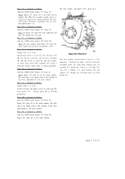
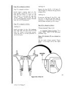
(2) The pin holes to be drilled for the new
sleeve should be located 60 degrees clockwise or
counterclockwise from the original pin holes. The
two alternate pin locations are indicated by the bro-
ken line in Fig. 149.1.
(3) Install sleeve 18 (Fig. 373, fold-out 2),
pressing it flush with the housing outer surface.
(4) Using a 1.1855-0.1875 drill, drill a hole
0.410 to 0.470-inch deep at one of the alternate loca-
tions chosen. This hole should be 0.250-inch inward
from the cover mounting surface and at a 30 degree
angle to the cover mounting surface. Refer to Figure
149.1.
Back to Top

