TM-9-2520-234-35 - Page 13 of 323
Page 172 is changed as follows.
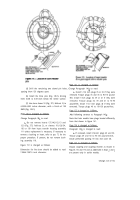
Add this NOTE below Figure 277 (Step 38).
Note . Figure 277 (Step 38) is for XTG 411-2A
models. For XTG 411-4 models, install eleven ex-
ternal-(A) and eleven internal-splined (B) left-
brake plates alternately, beginning with an exter-
nal-splined plate (A).
Page 175 is changed as follows.
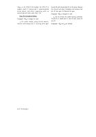
Add this NOTE below Figure 287 (Step 48).
Note. In Figure 287 (Step 48), later models do not
have the shroud over the gear.
Page 177 is changed as follows.
Add this NOTE below Figure 295 (Step 56).
Note. For later models, skip Figure 295 (Step 56).
Later models do not have accumulator valves.
Page 182 is changed as follows.
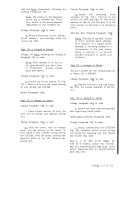
Change Step 78 to read:
Install nine 3/8-16 x 3-1/4 (A), five 3/8-16x 4-1/2
(B), one 3/8-16 x 2-1/2 (C), nine 3/8-16 x 2-3/4-inch
(D) and four 3/8-16 x 4 bolts (E) with lock washers
to retain relay valve body assembly (F). Using a
9/16-inch wrench, torque bolts to 20-26 pound-feet.
Page 186 is changed as follows.
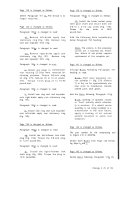
Add this NOTE below Figure 333 (Step 6).
Note. Figure 333 (Step 6) are for earlier models.
The lock strip is no longer used at this location. It
has been superseded by two lock washers.
Page 188 is changed as follows.
Change Step 11 to read:
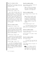
Install scavenge oil pump screen (A) and plug (B)
with gasket (C).
Torque plug (B) to 90-100
pound-feet.
Page 190 is changed as follows.
Add this NOTE below Figure 349 (Step 22).
Figure 349 (Step 22) is for earlier models. The lock
strip is no longer used at this location. It has been
superseded by two lock washers.
Page 191 is changed as follows.
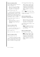
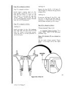
Add this NOTE below Figure 353 (Step 26).
Figure 353 (Step 26) is for earlier models.
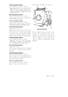
For later models, add Figure 353.1 (Step 26.1):
For later models, install twelve 7/16-14 x 1-1/2
converter
housing-to-input transfer housing
assembly bolts (A) with lock washers (B). At
locations (C), install four 7/16-14 x 1-5/8 bolts 155
(fig. 373.1, foldout 2.1), lock washers 156 and
spacers 157. Torque the 7/16-inch bolts to 42-50
pound-feet.
Change 2 (9 of 13)
Back to Top

